Sep 29, 2026
Last Updated: September 29, 2026
Testing aerospace part tolerances is the process of measuring a finished component against its design specification to confirm it falls within the permitted limits of size, form, and position. Get it wrong and a bracket that looks perfect can fail inspection, grounding a build programme. This guide from 76 ADDITIVE explains the standards, equipment, and methods that govern how to test aerospace part tolerances in 2026, from first-article inspection through to production sign-off.
Aerospace tolerances are unforgiving because the consequences of a bad part are severe, and the paperwork trail matters as much as the measurement itself. Below, we break down GD&T, metrology equipment, AS9100 quality requirements, and the additive manufacturing question that trips up most newcomers.
Aerospace tolerances are critical because a component that sits outside its specified limits can compromise fit, fatigue life, and safety, and the failure may not appear until the part is already in service. Unlike consumer goods, aerospace parts often carry safety consequences that make rework or scrap the only acceptable outcomes for out-of-spec work.
The numbers involved are small. A typical machined bracket might be specified to a few hundredths of a millimetre, and surface finish and hole position matter as much as overall dimensions. That is why aerospace buyers ask for full dimensional reports rather than a simple pass or fail.
There is also a commercial dimension. A part that fails inspection late in the build sequence can hold up an entire assembly, and the cost of that delay usually dwarfs the cost of the part itself. Inspection is not a formality; it is risk control.
GD&T standards for aerospace are the rulebook that tells an inspector what a drawing actually means. Geometric Dimensioning and Tolerancing (GD&T) is a symbolic language used on engineering drawings to define the allowable variation in form, orientation, location, and runout of a feature. Without it, a drawing is open to interpretation, and two inspectors can reach two different verdicts on the same part.
In aerospace, the most widely referenced framework is the ASME Y14.5 standard, which defines the symbols, datums, and tolerance zones used across drawings. Many aerospace primes also work to company-specific supplements layered on top of the base standard, so always confirm which revision a drawing calls for before you measure anything.
The practical point for anyone learning how to test aerospace part tolerances is this: you cannot inspect a part correctly until you can read the drawing correctly. Datum selection, material condition modifiers, and feature control frames all change what "in tolerance" means.
Metrology equipment for aerospace inspection ranges from handheld gauges to large-scale coordinate measuring machines, and the right choice depends on the feature, the tolerance, and the volume of parts you need to check. No single instrument covers every job.
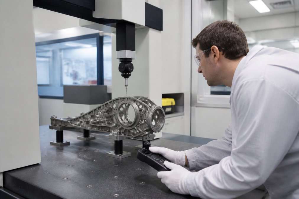
Common categories include:
The instrument must always be capable of measuring to roughly one-tenth of the tolerance it is checking. If your tolerance is tight and your gauge is coarse, the measurement tells you nothing useful.
Tolerance testing follows a repeatable sequence: interpret the drawing, establish datums, select the instrument, measure, compare, and document. Skipping a step is how inspection errors creep in.
Expected result: a complete dimensional report that another inspector could reproduce from the same part and drawing.
Aerospace quality assurance standards AS9100 define the quality management system requirements that aerospace suppliers are expected to work to. AS9100 is built on the ISO 9001 foundation and adds aerospace-specific requirements around risk management, traceability, and configuration control. Certification is often a condition of doing business with aerospace primes.
For tolerance testing specifically, AS9100 drives several practical obligations:
The standard does not tell you which instrument to use. It tells you that whatever you use must be controlled, calibrated, and documented. That distinction matters when you are setting up an inspection process from scratch.
Additive manufacturing changes the tolerance testing conversation because the process produces parts differently from machining, and the tolerances you can hold depend on the technology and orientation. Powder bed fusion and resin-based processes each have their own achievable limits, and those limits vary by feature type and build direction.
For low and mid-volume production, this is where additive earns its place. At 76 ADDITIVE, we produce end-use components using MJF and Carbon DLS technology, which suits teams that need repeatable parts without committing to tooling. The inspection logic stays the same: measure against the drawing, document against the standard. What changes is which features are critical and how the build orientation affects them.
If you are coming from injection moulding, expect to think about anisotropy, surface finish on down-facing surfaces, and minimum feature sizes differently. A test batch is usually the fastest way to confirm your geometry is viable before committing to volume.
The most common mistakes in tolerance testing are procedural, not technical. Teams measure the wrong feature, use an instrument that is too coarse, or document results in a way that cannot be audited.
Watch for these:
A common mistake is assuming additive parts cannot hold aerospace tolerances at all.
Standard tolerances vary by application and material. Typical aerospace tolerances range from ±0.005 mm to ±0.1 mm for critical dimensions, but high-precision parts can require ±0.001 mm. Always refer to the engineering drawing and AS9100 requirements, as tolerances are defined by design intent and safety factors. Additive manufacturing can achieve these levels with proper process control.
Verification starts with a coordinate measuring machine (CMM) or optical comparator to check critical dimensions against GD&T callouts. For internal features, industrial CT scanning provides non-destructive inspection. It's essential to validate the printing process itself, as layer orientation and thermal effects can introduce anisotropy. Regular calibration and statistical process control ensure repeatability.
Essential tools include coordinate measuring machines (CMMs), optical comparators, laser scanners, and micrometers. For complex geometries, CT scanners are invaluable. Height gauges and surface roughness testers are also common. The choice depends on part size, feature accessibility, and tolerance tightness. Many aerospace firms use a combination to cross-verify results.
GD&T provides a universal language for defining allowable variation, reducing ambiguity in inspection. It ensures that parts fit and function as intended, which is vital for safety and interchangeability. Compliance with GD&T standards like ASME Y14.5 is often required by aerospace quality assurance standards AS9100, and it facilitates communication between design, manufacturing, and inspection teams.
Additive manufacturing introduces unique variables such as layer thickness, build orientation, and thermal distortion. Testing protocols must account for these by including test coupons and in-situ monitoring. Post-processing steps like machining may be needed to meet tight tolerances. With proper process validation, additive parts can meet aerospace tolerances, often with fewer constraints than traditional methods.
Challenges include accessing internal features, dealing with complex geometries, and avoiding measurement-induced distortion. Temperature fluctuations can also affect readings, so controlled environments are necessary. Additionally, the cost of metrology equipment and the need for skilled operators are significant. Using the right tool for each feature and following a documented inspection plan mitigates these issues.
Opening Hours (our printers run through the night)
Monday - Friday, 9am - 5pm


76 Additive
19 Hall Barn Road Industrial Estate
Isleham, Ely
Cambridgeshire, CB7 5RJ
76 Projects t/a 76 Additive
Registered in England & Wales Company no: 10235633
VAT: 245 830 796